
Power Generation Process Basics major components for a 600-megawatt coal-fired power plant.
* 1. Rail Unloading House
* 2. Junction House
* 3. Coal Conveyor
* 4. Boiler Coal Bunker
* 5. Bucket Wheel Machine
* 6. Coal Feeder
* 7. Pulverising Mill
* 8. Primary Air Fan
* 9. Boiler Burner
* 10. Boiler
* 11. Forced Draught Fan
* 12. Air Heater
* 13. Electrostatic Precipitator
* 14. Induced Draught Fan
* 15. Main Chimney
* 16. Superheater
* 17. High Pressure Turbine
* 18. Boiler Reheater
* 19. Intermediate Pressure Turbine
* 20. Low Pressure Turbine
* 21. Rotor
* 22. Stator
* 23. Generator Transformer
* 24. Condenser
* 25. Condensate Extraction Pump
* 26. Low Pressure Feed Heaters
* 27. Deaerator
* 28. Boiler Feed Pump
* 29. High Pressure Feed Heaters
* 30. Economiser
* 31. Steam Drum
* 32. Cooling Tower
* 33. Circulating Water Pumps
* 34. Circulating Water Make-Up Pumps
* 35. FGD Absorber Tower


1. Rail Unloading House
Coal is transported to the station by coal trains of typically 1,400 tonnes capacity and discharged through bottom hoppers, which open automatically whilst the train is in motion.
Averaging out our coal deliveries over the year, we have around 140 trains unloading coal each week!
Coal is transported to the station by coal trains of typically 1,400 tonnes capacity and discharged through bottom hoppers, which open automatically whilst the train is in motion.
Averaging out our coal deliveries over the year, we have around 140 trains unloading coal each week!

2. Junction House
At the junction house, coal can be sent to or retrieved from the stockpile, or sent to the coal bunkers.
To make sure that we can generate electricity when we want to, we have to make sure the coal is in the right place at the right time. To do this we have a team of people whose job it is to handle the movement of coal.

3. Coal Conveyor
Coal conveyors are used to move coal around efficiently. Coal arriving by train can be stocked for later use or taken straight to the coal bunkers. An automatic control system helps to ensure that the conveyors take the coal to the right bunkers.
Our main coal conveyors can move 3,800 tonnes of coal every hour. This is enough coal to cover ten football pitches to a depth of 50mm.

4. Boiler Coal Bunker
Each coal bunker supplies coal to two pulverising fuel mills. Each bunker can hold 1,000 tonnes of coal, and there are five bunkers per unit.
Power station coal is not as lumpy as coal used in the home. Typically around half of it is less than 12.5 millimetres across and 95% is less than 50 millimetres.

5. Bucket Wheel Machine
Bucket wheel machines are used to put coal out to the stockpile and reclaim coal from the stockpile. A bucket wheel machine can move approximately 3,000 tonnes of coal in an hour.
The wheel is 9 metres in diameter and has nine buckets. One schoolchild once told us that she thought it looked like a giant sunflower, what do you think it looks like?

6. Coal Feeder
The variable speed coal feeder feeds coal from the bunkers to the mill via a 450 millimetre diameter pipe. It uses a conveyor to move coal through a fixed gap at a precisely controlled speed. Varying the speed controls the amount of coal supplied to the boilers.
These are precision bits of equipment that have to move exact amounts of coal. They can move 40 tonnes of coal in an hour!

7. Pulverising Mill
Each of the six units at Drax has ten pulverising fuel mills, each capable of pulverising 36 tonnes of coal per hour. Inside the mills, ten giant hollow steel balls, each 1.4 tonnes in weight and approximately 730 millimetres in diameter, crush the coal into a fine powder.
Crushing the coal into a fine powder makes it easier to burn it more completely. When the hollow mill balls are new their wall thickness is between 127 and 135 millimetres. In 42 to 58 thousand hours we wear them down to around 45 millimetres in thickness.

8. Primary Air Fan
Air to blow the coal from the mill to the boiler, called the primary air, is supplied by a large fan driven by a 3,300 volts variable speed motor.
Did you know that when mixed with a stream of air the powdered coal behaves more like a gas than a solid?
Air to blow the coal from the mill to the boiler, called the primary air, is supplied by a large fan driven by a 3,300 volts variable speed motor.
Did you know that when mixed with a stream of air the powdered coal behaves more like a gas than a solid?

9. Boiler Burner
Propane is fed to the burner where it is lit by a spark plug. Fuel oil is then fed to the burner and is burned by the propane flame. Once a stable flame is established the coal/air mix is blown through the burner where it lights spontaneously. The propane and oil are then shut off. In 2003, we completed the replacement of all the original burners with low NOX burners to reduce the amount
of oxides of nitrogen produced.
The propane burners are used to start the boiler up, a bit like firelighters. At full output the power station can burn around 36,000 tonnes of coal a day – that’s a lot of powder!”

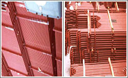
10. Boiler
To produce steam each boiler converts energy, in the form of coal, into steam at a rate of 563 kilogrammes per second. The boiler is lined with steel tubing in which pure boiler feed water is turned to steam by the heat created from the combustion of coal.
Each boiler is as high as a 15 storey modern office building and weighs 4,000 tonnes. Inside the boiler there is enough steel tubing to stretch the 480 kilometres (300 miles) from London to Newcastle.

11. Forced Draught Fan
Each unit has two forced draught fans. The fans draw warm air from the top of the boiler house through large air heaters becoming the primary and secondary air used for the boiler combustion process. The air heater warms the incoming air by transferring heat energy from the outgoing flue gases.
Even in the winter the temperature of the top of the boiler house is in the 30s (°C), so we are making good use of hot air that would otherwise be wasted.

12. Air Heater
The air heaters use the remaining heat energy in the flue gas to heat up the combustion air for the boiler. Efficiency is increased by using this heat that would otherwise go up the chimney. The air temperature leaving the air heaters is at 294°C.
The air heaters use the remaining heat energy in the flue gas to heat up the combustion air for the boiler. Efficiency is increased by using this heat that would otherwise go up the chimney.

13. Electrostatic Precipitator
Each boiler has three precipitators which contain high voltage electrodes, these attract the dust or pulverised fuel ash (PFA) from the flue gases. At regular intervals the electrodes are rapped with motor-driven hammers and the PFA falls into hoppers below. In a year we would expect to produce 1.4 million tonnes of PFA.
This is one of the ways that we clean up the flue gases or smoke that we send up the chimney. The best thing is that, once collected, the PFA is not wasted, we sell most of it to the construction industry for use in building materials.

14. Induced Draught Fan
Two induced draught fans draw gases out of the boiler. The gas has already passed through the air heaters and precipatators before it has reached these fans.
The heat from the flue gases or smoke is used in the air heaters to heat up the primary and secondary air.
Two induced draught fans draw gases out of the boiler. The gas has already passed through the air heaters and precipatators before it has reached these fans.
The heat from the flue gases or smoke is used in the air heaters to heat up the primary and secondary air.

15. Main Chimney
The main chimney is 259 metres high and 44,000 tonnes of reinforced concrete were used to make it. It consists of three elliptical flues each of which serves two boilers. The flues are re-shaped to a circular section of 9.1 metres at the point where they emerge from the top of the chimney to extend another 9.1 metres.
Our chimney used to be the highest industrial chimney in the world and was in the Guinness Book of Records, but now it is only the tallest in the country. It is 101 metres higher than the Blackpool Tower, 15 metres taller than Canary Wharf, but 41 metres shorter than the Eiffel Tower.

16. Superheater
The steam produced in the boiler goes to the steam drum and is then piped through the primary, platen and final superheaters where it reaches the outlet temperature of 568°C and 166 bar pressure.
At this point in the process we have now turned the water into a very powerful source of energy.
The steam produced in the boiler goes to the steam drum and is then piped through the primary, platen and final superheaters where it reaches the outlet temperature of 568°C and 166 bar pressure.
At this point in the process we have now turned the water into a very powerful source of energy.

17. High Pressure Turbine
High pressure steam at 565°C and 156 bar pressure passes through the high pressure turbine. The exhaust steam from this section is returned to the boiler for reheating before being used in the next section of the turbine set.
The blades in the high pressure turbine are the smallest of all the turbine blades, this is because the incoming steam has very high energy and occupies a low volume. The blades are fixed to a shaft and as the steam hits the blades it causes the shaft to rotate.
18. Boiler Reheater
After expanding through the high pressure turbine the exhaust steam is returned to the boiler at 360°C and 42 bar pressure for reheating before being used in the intermediate pressure turbine.
The reheater reheats the steam from a temperature of 360°C back to 568°C.
After expanding through the high pressure turbine the exhaust steam is returned to the boiler at 360°C and 42 bar pressure for reheating before being used in the intermediate pressure turbine.
The reheater reheats the steam from a temperature of 360°C back to 568°C.

19. Intermediate Pressure Turbine
On leaving the boiler reheater, steam enters the intermediate pressure turbine at 565°C and 40.2 bar pressure. From here the steam goes straight to the next section of the turbine set.
The steam has expanded and has less energy when it enters this section, so here the turbine blades are bigger than those in the high pressure turbine. The blades are fixed to a shaft and as the steam hits the blades it causes the shaft to rotate.

20. Low Pressure Turbine
From the intermediate pressure turbines, the steam continues its expansion in the three low pressure turbines. The steam entering the turbines is at 306°C and 6.32bar. To get the most work out of the steam, the exhaust pressure is kept very low, just 50 millibar above a complete vacuum.
The tip speed of the largest blades with the shaft spinning at 3000 revolutions per minute is 1,285 miles per hour, or 1.6 times the speed of sound.

21. Rotor
The shaft that runs through the turbines is coupled to the rotor, which is a large electromagnet inside a cylinder of copper windings called the stator.
The rotor weighs 86 tonnes and rotates at 3,000 revolutions per minute.
The shaft that runs through the turbines is coupled to the rotor, which is a large electromagnet inside a cylinder of copper windings called the stator.
The rotor weighs 86 tonnes and rotates at 3,000 revolutions per minute.

22. Stator
As the electromagnet rotates inside the copper windings, a magnetic field is created which induces a three phase alternating electric current (AC) in the stator windings. Together the rotor and stator are known as the generator. The stator weighs 305 tonnes.
Electricity is generated at 23,500 volts, that’s over 100 times the voltage in your home!

23. Generator Transformer
From the generator the electricity then goes to a transformer where the voltage is increased to 400,000 volts before sending it via cables to the National Grid sub-station for distribution around the country.
Each of our units is capable of generating enough electricity in a year to power around one million homes.

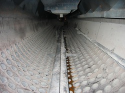
24. Condenser
With its useful energy spent in the turbines the steam then passes to two pannier mounted condensers where it is condensed back into water and pumped back to the boiler via a series of low pressure and high pressure feed heaters.
The condenser is made up of thousands of tubes full of river water, the hot steam passes across the cold surface of the tubes and the steam is condensed back into water.

25. Condensate Extraction Pump
The condensate water is drawn from the condenser by the extraction pump and sent to the low pressure feed heaters.
This is how we begin to get the water back to the boiler so that the whole process can start again.
The condensate water is drawn from the condenser by the extraction pump and sent to the low pressure feed heaters.
This is how we begin to get the water back to the boiler so that the whole process can start again.

26. Low Pressure Feed Heaters
Feedwater from the condenser extraction pumps passes through five low pressure feed heaters. Steam is used to heat the feedwater. After the fifth feedheater, the feedwater is at around 160°C.
These feed heaters are increasing the water temperature before this water returns to the boiler.
Feedwater from the condenser extraction pumps passes through five low pressure feed heaters. Steam is used to heat the feedwater. After the fifth feedheater, the feedwater is at around 160°C.
These feed heaters are increasing the water temperature before this water returns to the boiler.

27. Deaerator
From the low pressure feed heaters the water passes through the deaerator before going to the high pressure feed heaters.
In the deaerator, the gases are removed from the water to limit corrosion or rusting of the steel tubing that carries the water back to the boiler and lines the boiler.
From the low pressure feed heaters the water passes through the deaerator before going to the high pressure feed heaters.
In the deaerator, the gases are removed from the water to limit corrosion or rusting of the steel tubing that carries the water back to the boiler and lines the boiler.

28. Boiler Feed Pump
The boiler feed pump pumps water into the boiler, overcoming the boiler pressure of 160 bar to achieve it. The pump is driven by a steam turbine and runs at 7,500 revolutions per minute.
These are powerful pumps, they can move water at the astonishing rate of 568 litres every second and could produce a fountain that's a mile high!

29. High Pressure Feed Heaters
With a similar purpose to the low pressure feed heaters, the high pressure feed heaters are the last stage of feedwater heating before the feedwater enters the boiler system at the economiser. Feedwater leaving these heaters is at 252°C.
The heaters are increasing the temperature of the feedwater before it enters the boiler system

30. Economiser
Flue gases leaving the superheater and reheater still contain useful energy. Water from the high pressure feed heaters is heated in the economiser from 252°C to 292°C before it continues to the steam drum. Having given up its last heat in the boiler, the flue gases move on to the air heater.
The economiser makes use of the heat energy that is still in the flue gas to increase the temperature of the feedwater further before it goes to the steam drum.
31. Steam Drum
After leaving the economiser, the feedwater reaches the steam drum, which is a cylindrical vessel at the top of the boiler. From here the water flows by natural circulation through downpipes into the boiler. Saturated steam collects here ready to go to the superheater.
The steam drum is simply a huge tank 30.5 metres long that holds both water on its way into the boiler and steam ready to be superheated. It's vital to keep a level of water in the steam drum, otherwise the boiler will very quickly overheat.

32. Cooling Tower
The warm river water is taken from the condenser tubes to about a quarter of the way up the 114 metre high cooling tower where it is dropped through honeycombed plastic packing. This breaks the water up into a very fine spray, increasing the surface area of the water droplets making it easier to cool.
The cooling tower is designed as a natural draught chimney, drawing cold air from outside through the falling water. The now cool river water is collected in the 95 metre diameter pond at the bottom of the cooling tower and from here it is either pumped back to the condensers or periodically is purged back to the river.
What you see coming out of the top of the cooling tower is simply clean, warm water vapour NOT smoke! And did you know that the base of each cooling tower could hold the dome of St. Paul's Cathedral or nearly two Olympic-sized swimming pools!

33. Circulating Water Pumps
The circulating water pumps are used to circulate the water from the cooling tower to the condenser and back again.
One circulating water pump can move 880 tonnes of water in one minute, that's enough to fill 2,700 baths!
The circulating water pumps are used to circulate the water from the cooling tower to the condenser and back again.
One circulating water pump can move 880 tonnes of water in one minute, that's enough to fill 2,700 baths!

These pumps are used to supply water from the River Ouse. Before going to the cooling tower the silt is removed in large sedimentation tanks.
The power station uses 160 million litres of water from the river every day, half of which is returned to the river cleaner than when it was taken!
The power station uses 160 million litres of water from the river every day, half of which is returned to the river cleaner than when it was taken!

After passing through the electrostatic precipitators, the boiler flue gas is increased in pressure and then cooled from between 115°C-130°C to 80°C. It enters the lowest part of the absorber and is further cooled by water used to wash the inlet duct to prevent a build up of solids.
The main SO2 absorption process, and the washing out of any remaining pulverised fuel ash, occurs as the gas is ‘scrubbed’ by the recirculating limestone slurry. This is taken from the bottom of the absorber and is sprayed downwards from nozzles arranged at five separate levels in the absorber tower. As a result of the process chemistry, the recirculating slurry becomes predominantly gypsum and a portion is continuously pumped away for gypsum separation and the removal of water using a hydrocyclone system. A waste water treatment plant ensures any water from the FGD process returned to the river meets quality standards set by the regulatory authority.
The cleaned flue gas is raised in temperature and discharged up the 259 metre high chimney which has been lined with titanium plate. At full operation, some 280,000 tonnes of SO2 per year can be removed from the chimney gases.
